Aberrations
Aberrations are errors in an image that occur because of imperfections in the optical system. Another way of saying this is that aberrations result when the optical system misdirects some of the objectís rays. Optical components can create errors in an image even if they are made of the best materials and have no defects. Some types of aberrations can occur when electromagnetic radiation of one wavelength is being imaged (monochromatic aberrations), and other types occur when electromagnetic radiation of two or more wavelengths is imaged (chromatic aberrations). The origins and consequences of chromatic radiation were discussed in the previous section.
Monochromatic aberrations can be grouped into several different categories: spherical, coma, astigmatism, field curvature, and distortion.The idea of reference sphere is often used in discussions of aberrations. For all spheres, a ray drawn perpendicular to the sphereís surface will intersect the center of the sphere, no matter what spot on the surface is picked.
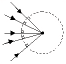
Sphere with rays drawn perpendicular to the surface intersect at the center of the sphere.
A reference sphere isnít a physical structure; itís just a mathematical construct that the wavefront of the electromagnetic radiation is compared to. If the electromagnetic wavefront has the shape of the reference sphere, then the wavefront will come to a perfect focus at the center of the sphere. Remember that the definition of a ray specifies that rays are drawn perpendicular to the wavefront. All of the rays associated with a spherical wavefront will intersect at the center of the sphere. If the wavefront is not spherical, some of the rays will pass through the center of the sphere.
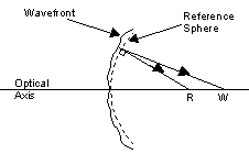
Some rays on an aberrated wavefront focus to a different point, W, than do rays that are perpendicular to the reference sphere.
By comparing the wavefront of the electromagnetic radiation with the reference sphere, it is possible to determine what aberrations are present in an image and how severe they are.
Spherical Aberration
Spherical aberrations occur for lenses that have spherical surfaces. Rays passing through points on a lens farther away from an axis are refracted more than those closer to the axis. This results in a distribution of foci along the optical axis.
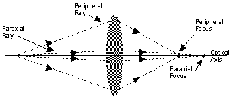
Spherical aberrations result in paraxial and peripheral rays having different foci.
Rays that make a small angle with the optical axis, and which travel close to the axis, are called paraxial rays. Peripheral rays interact with the edges of the components in an optical system. When a wavefront is spherically aberrated, peripheral rays focus closer to the lens than paraxial rays do. The difference between where these two types of rays come to a focus is a way to measure the severity of spherical aberration in a system.
It is possible to design optical components with aspherical surfaces that are free of spherical aberration. Gradient-index lenses, which have refractive indices that are highest at the center of the lens and gradually decrease closer to the edge of the lens, can also eliminate spherical aberration. However, optical components with spherical surfaces are much easier and cheaper to manufacture than those with aspherical surfaces or gradient-index characteristics. Because of this, most designers of optical systems use off-the-shelf components with spherical surfaces.
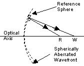
A measure of the spherical aberration of the optical system is the physical distance between the foci of the reference sphere and of the peripheral rays of the aberrated wavefront (between R and W).
When multiple-lens systems are designed, optical designers use the interactions of all of the system components to minimize spherical, as well as other, aberrations. The undercorrection of one lens can be used to compensate for the overcorrection of an other lens. If the optical system must contain only one spherical lens, the spherical aberration can be minimized if both lens surfaces contribute equally to the power of the lens. Making a lens with large radii of curvature will also help minimize spherical aberration.
Coma
Spherical aberrations describe where different points focus along the optical axis. The image of an object point that lies off of the optical axis will form a tear-drop shaped image. The flared tail of the image is usually directed away from the axis, but it can also be oriented towards the axis.
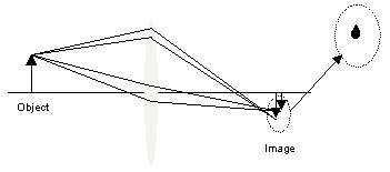
Coma blurs the image of an off-axis point into the shape of a teardrop.
When an object is imaged by a lens that suffers from coma, rays that pass through the periphery of the lens form a larger image than the rays that pass through the lens closer to the axis. Correcting for coma requires that the different images are made to overlap. In effect, the images formed by the paraxial and the peripheral rays need to experience different degrees of magnification.
Coma can be minimized by carefully specifying the radii of curvature of the two sides of a single lens, or by using a combination of optical elements. When an optical system has no spherical aberration or coma, it is called aplanatic.
Astigmatism
Rays that are emitted from an object point form a right circular cone as they travel towards a lens. When the object point is located off-axis, this cone of rays forms an ellipse on the surface of the lens. (If the cone of rays had been emitted from an on-axis object point, they would have formed a circle on the surface of the lens.) The tangential plane intersects the major axis of the ellipse, and it contains both the optical axis and the object point. The sagittal plan is oriented perpendicular to the tangential plane.
Because of the different ways in which they intersect the lens, the rays in the tangential plane and the rays in the sagittal plane effectively experience lenses different focal lengths. The effective lens that the rays in the tangential plane experience has a higher power. Because of this asymmetry, the rays in the tangential plane focus closer to the lens than the sagittal rays.
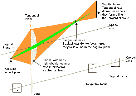
The top figure depicts how a system suffering from astigmatism focuses a cone of rays from an off-axis point onto the tangential and sagittal planes. The bottom figure places a viewing screen at the object point, the tangential focus, and sagittal focus.
The location of the image points for the tangential and sagittal rays coincide on the optical axis, and they diverge for points farther from the optical axis.
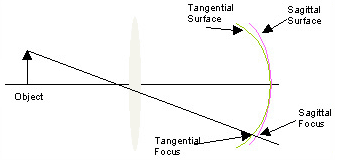
Astigmatism causes rays in the tangential plane focus on a different surface than rays in the sagittal plane.
Field Curvature
Field curvature (or curvature of field) is an aberration that is related to astigmatism, but it can exist in a system that does not suffer from astigmatism. In the case of field curvature, the object is imaged on a curved surface, rather than on a plane. The image is not blurred by this aberration; it is just projected onto a curved surface. This is a problem for cameras and slide projectors, because the image plane needs to be flat for these applications. The curved image field can be flattened by using a combination of lenses. If two lenses are used, their indices of refraction (n1 and n2) and their focal lengths (f1 and f2) must meet the following condition:
n1f1 + n2f2 = 0.
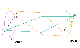
If a system exhibits field curvature, objects are imaged onto a curved image plane.
Distortion
Like field curvature, an image suffering from distortion is not blurred. Instead, the image points are displaced radially from the positions predicted when paraxial rays are traced through the optical system. The image points may be displaced either towards or away from the optical axis. This effect suggests that the various parts of the object experience different magnifications.
In pincushion distortion, the magnification increases along the indicated directions. An image of a square suffering from pincushion distortion would have drawn-out corners.
In barrel distortion, the magnification decreases along the indicted directions. An image of a square suffering from barrel distortion would be characterized by retraced corners.
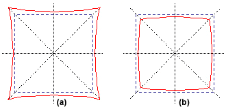
Pincushion distortion pinches and stretches the image of a square at the corners (a). Barrel distortion pushes the corners of an image of a square in towards the center (b).
References:
Jugen R. Meyer-Arendt, Introduction to Classical and Modern Optics, Prentice-Hall Inc.: Engelwood Cliffs, NJ (1989).
Bryan Stone, OPT 441: Geometrical Optics Class Notes; University of Rochester: Rochester, NY (1998).
Bahaa E. A. Saleh and Malvin Carl Teich, Fundamentals of Photonics, John Wiley & Sons, Inc.; New York (1991).


