Fermatís Principle
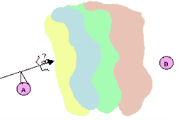
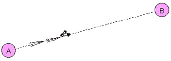
Rays are traced through an optical system using Fermatís Principle, which says that the rays of EM Rad follow only the fastest route when they travel from one point (A) to another (B). If more than one path is the fastest, then the EM Rad will follow all of them.

Fermatís Principle predicts what route a ray will take through an optical system.
A material property called the refractive index, denoted by the letter Ďní, is the key to applying Fermatís Principle. The refractive index of a material is a way of describing how fast EM Rad can travel in it. Just as you can run faster on dry ground than you can when you are up to your neck in water, EM Rad can travel faster in some materials than in others. EM Rad experiences its top velocity in vacuum, ~3x10⁸ m/s, which is called the Ďspeed of light in vacuumí or sometimes just the Ďspeed of lightí, and is denoted by the letter Ďcí. EM Rad travels at slower velocities in all other materials. The refractive index is computed by dividing the speed of light in vacuum by the speed of EM Rad in the material:
n = c/v
where v is the velocity of light in the material. Because both c and v have the same units, m/s, the index of refraction is unitless. The slower light travels in a material, the higher the refractive index of the material. Air has a smaller refractive index (1.0003) than water (1.33). The refractive indices of many common materials are easy to find tabulated in optical references.
The time, Ďtí, taken to travel a distance, Ďdí, in a material of refractive index, Ďní, is
t = n d/c.
Fermatís Principle is easy to use if a ray of EM Rad is travelling in a medium that has the same index of refraction everywhere. In this case, just draw a straight line between the two points!

Rays follow a straight line when they travel between two points in a medium with a uniform refractive index.
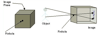
A pinhole camera can be easily designed using the concept of rays and the knowledge that rays travel in straight lines through uniform media. A pinhole camera is a box with 6 opaque sides. One side has a small hole cut in it, and the opposite side has a piece of photographic film affixed to it. Cover the hole until you are ready to take your picture. The pinhole camera works because the small pinhole will accept very few rays from each point on the object Ė it is almost as if each point on the object contributes one ray to the image. Because the pinhole lets in so few rays, it will take a few seconds for the image to be recorded by the film. This is too long to hold a camera steady in your hands - the image will turn out blurry if you do. Instead, take the picture while the camera is sitting on a steady surface. By sketching a diagram of your pinhole camera with a ray extending from each point on the object through the pinhole and on to the film you can see how large your image will be Ė you will be able to predict that your image will be inverted!

On the left is a sketch of the outside of a pinhole camera. The film is placed inside of the box on the image plane. On the right is a sketch showing how a pinhole camera images an object.
For those of you who would like to see the mathematical way of stating Fermatís principle, it can be expressed by saying that the optical path length, computed using the optical path integral

is an extremum when compared to neighboring paths. Writing the refractive index as n(r) refers to the fact that it is a function of position.


