Lenses and Mirrors
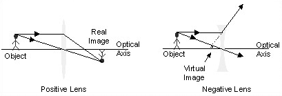
A lens is a transparent device with two curved surfaces, usually made of glass or plastic, that uses refraction to form an image of an object. Mirrors, which have curved surfaces designed to reflect rays, also form images. A system of lenses and/or mirrors forms an image by gathering rays from an object and then causes them to converge or diverge. The position to which the rays converge to or diverge from is the image. A real image is formed when the optical system causes the rays to converge to a point, a virtual image is formed at the location from which they seem to originate.

Depictions of lenses forming real and virtual images. Positive and negative lenses can both form real and virtual images.
The effects of lenses and mirrors on a ray can be determined using Fermatís Principle, through trigonometry and the application of Snellís Law, to trace the path of a light ray from a point on the source to the image point. This is done by 1) tracing a ray from the object to the first surface of the lens using trigonometry, 2) determining how the ray refracts at the first interface using Snellís Law, 3) tracing the ray to the second interface using trigonometry, 4) figuring out how it refracts at this surface using Snellís Law, 5) and then tracing the ray to the image location using trigonometry. At least two rays from each source point should be traced to determine the position of the image point. A matrix method based on these rules is frequently used to mathematically determine how rays propagate through an optical system.

Sketch showing the steps taken when propagating a ray through an optical system.
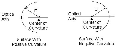
In general, the curvature of one side of the lens is different than that of the other side of the lens. The curvature of a lens surface is the inverse of the radius of curvature of the surface (c = 1/R). The curvature is positive when the center of curvature is to the right of the surface and negative when the center of curvature is to the left of the surface. Lenses or mirrors with flat surfaces are said to have an infinite radius of curvature.

Surfaces having positive and negative curvatures. R is the radius of curvature and c = 1/R is the curvature of the surface.
Although it is possible to buy lenses that have aspherically curved surfaces, the vast majority of lenses have spherically curved surfaces. Most optical systems use spherical lenses because they are easier to make and cheaper to buy than aspherical lenses. (See the following section on aberrations to find out why a lens designer might want to use aspherical lenses in an optical system.) Lens designers specify the curvatures, the thicknesses, and the refractive indices of the lenses to control the way that lenses image objects.
For a lens that has a very small thickness, called a thin lens, it is a good approximation to say that the lens has NO thickness. In this case, it is not necessary to propagate the ray from the first surface of the lens to the second (step 3 is omitted). The effect of the lens depends only on the difference in curvature of the two lens surfaces, so different thin lenses can have the same power. The power of a thin lens in air, f, is
f = (c1-c2)(n-1).
The focal length of that same thin lens in air is
f = 1/f.
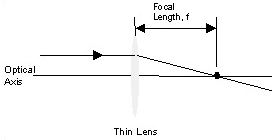
The focal length of a thin lens is the distance between the lens and the point at which the lens causes a ray, which was initially traveling parallel to optical axis, to intersect the optical axis.

Focal length of a thin lens
If a source is located very far away from a lens, all of the rays reaching that lens will be nearly parallel to one another. If the source is an infinite distance away, the rays will be completely parallel to one another. (The language of the Electromagnetic Wave Optics model says that these rays represent a plane wave). A bundle of rays of this kind could be used to find the focal length of a thin lens; the lens would focus them all down into one spot that would be easy to find. Lasers can be made to emit this kind of light. If you donít have access to a laser, you can still estimate the focal length of a lens using the sun (which is very far away from the earth) or even ceiling lamps (which are somewhat far away if you hold the lens at desk level).
A simple expression that describes how a thin lens images an object is called the Thin Lens Equation. It is a good way to figure out the location of an image if the distance between the object and the lens and the focal length of the lens are known. This equation assumes that air surrounds the object, image, and lens.

Thin Lens Equation
The image will not necessarily be the same size as the object. The size of the image (himage) is found by multiplying the size of the object (hobject) by the magnification of the system. The magnification of the thin lens system is

himage = m hobject
If the magnification is negative, then the image is inverted with respect to the object.
Mirrors can also be used to form images. They have a variety of curved surfaces, depending on their function. Popular shapes of telescope mirrors are paraboloids, hyperboloids, and prolate ellipsoids. Mirrors are widely used in telescope systems because they do not suffer from chromatic aberrations. (see the following section on dispersion to learn more about chromatic aberration.) One of the challenges in designing telescopes is to develop an optical system that images points off of the optical axis as well as it does objects on the optical axis. This is the same as saying that the designers are working to increase the field-of-view of the telescopes.
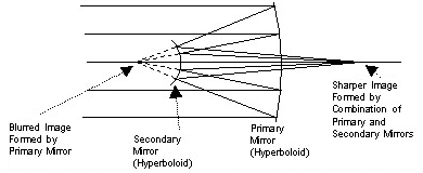
The Hubble space telescope has the form of a Ritchey-Chretien Telescope. This telescope increases its field-of-view by using a hyperboloids as both primary and secondary mirrors. The combination of the two mirrors are needed to form a good image, unlike other telescope designs which use a single paraboloid mirror to form a good image and a secondary mirror to direct the image to an eye or other detector. Astronauts had to install other optics in the Hubble as a way to correct for a defect in the curvature of the primary mirror that occurred during manufacturing.

Ritchey-Chretien telescope
Although many telescopes are made using mirrors, there are some that are made using lenses. The Keplerian Telesope is one of them. This telescope forms an inverted, internal image. Most binoculars are based on this design, and they use reflecting prisms to reinvert the image so that the image appears upright.

Keplerian telescope


